1.0 Purpose
Demonstrate the key innovations of ARRA’s Industrial Mesh technology
2.0 Feature Demonstration
Demonstrate the key innovations of ARRA’s Industrial Mesh technology
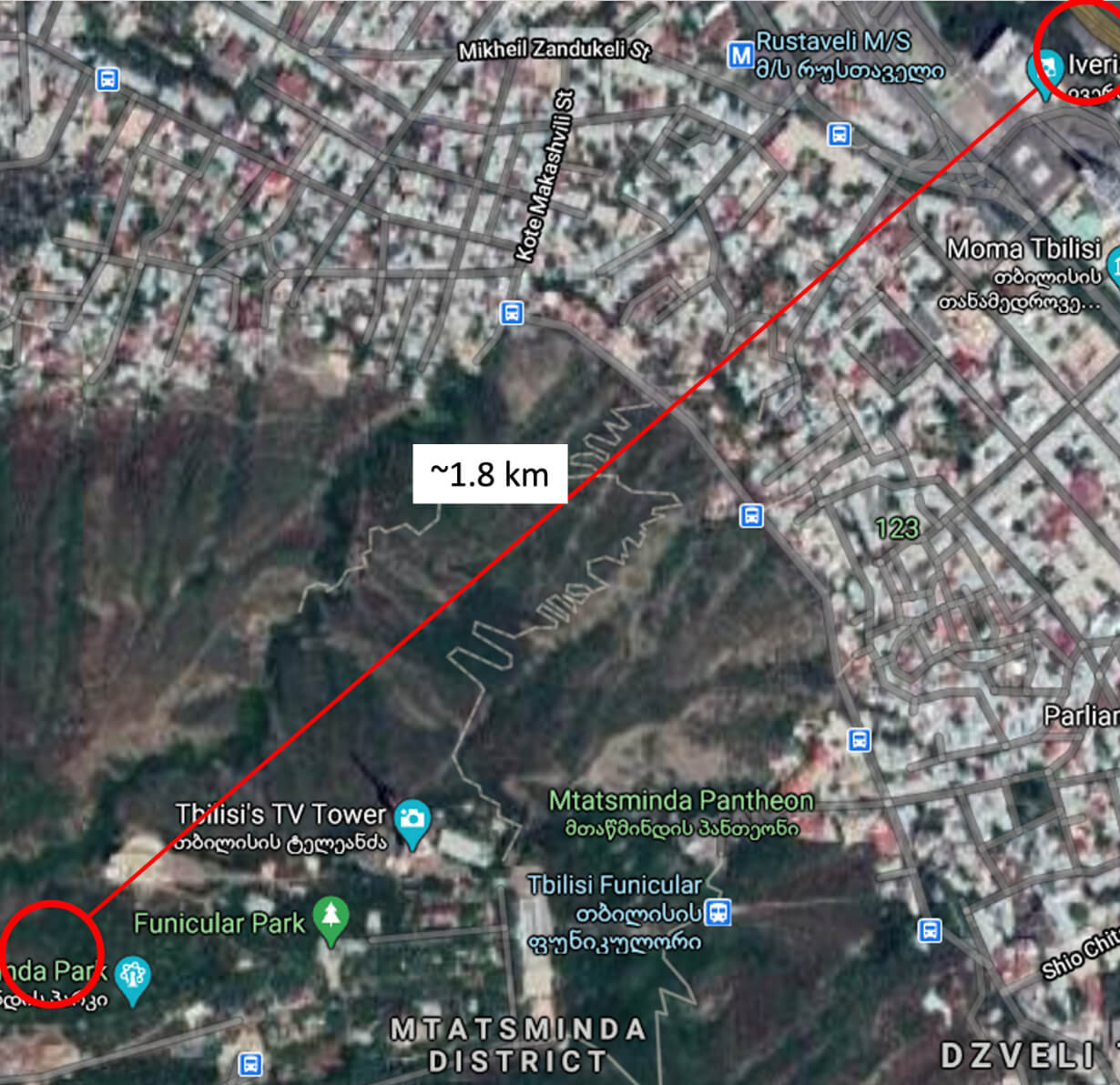
Description:
5 nodes were placed in a radio frequency congested urban city environment where 63 competing Wi-Fi signals were competing for dominance in the zone. ARRA routers were challenged to establish reliable wireless connections in this difficult environment and deliver high speed internet across the busy district. The fifth router, almost 2 kilometers away up the mountain, was added to demonstrate excellent long-range mesh capability.
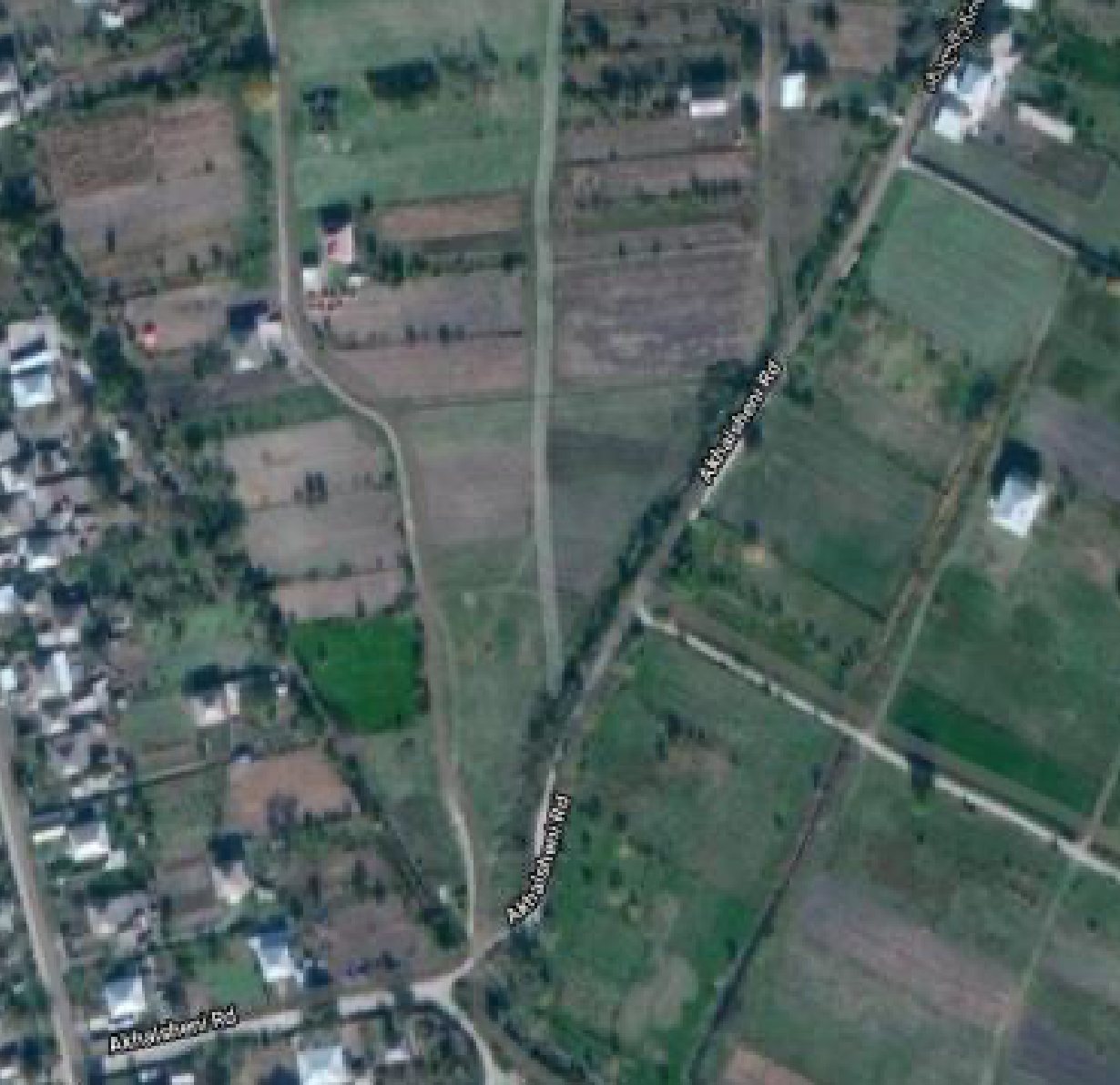
Description:
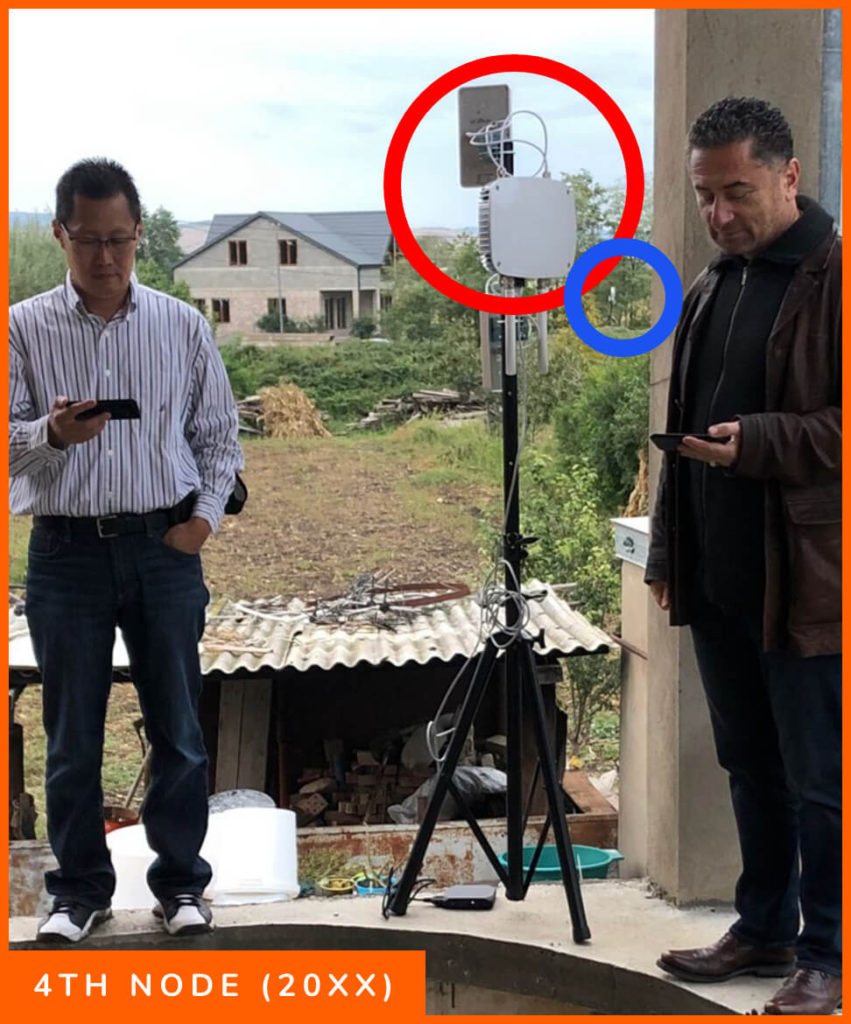
4 nodes were placed in a rural village using backhaul from a local resident. Each router was placed a good distance away and made to connect with little line of sight through trees and other obstacles where directionality of the panel antennas had to be done with guesswork.
Several local villagers found interest in the test effort and joined in to offer their homes to the test.
Summary of Demonstration
Feature | Purpose | Results | |
|---|---|---|---|
2.1 | Auto Configure Install | Show Automatic Setup. Power-on to operation without complexity | Empirically observed. Power-on, select ARRA Wi-Fi, captive portal, enter password, connect to internet, phone, email, etc. |
2.2 | Captive Portal | Show built-in business functionality | Presented Oct. 5: initial interaction with the ARRA network establishes the connection to the captive portal. |
2.3 | Self-healing Mesh | Network traffic automatically rerouted around downed nodes | Demonstrated Oct 6 in rural environment. |
2.4 | High-capacity Scalability | Five nodes under load with no signs of overhead stress | October 6 in rural environment, this reinforces the flexibility of the system when deployed. |
2.5 | Seamless Multi-homing | Show redundant auto-switching through alternate backhaul sources | Demonstrated October 6 by individually dropping intermediary node 20xx, and then 20zz without disrupting signal from 2010 to 200x |
2.6 | Deployment Flexibility | Deploy units around obstacles (hills/buildings) without costly towers | Demonstrated at both the casino deployment around the bar to the back room, and the rural deployment from the source (2010) to the node on the hill (20xx) then to the patio and the final node (20xx) |
2.7 | Long-range AP Performance | Show range connectivity behavior for end users | Demonstrated at the rural deployment by eight (12) users simultaneously playing video at the fourth node with minimal degradation from 27Mbs to 14Mbs |
2.8 | Long Range Capability | Show long-range node-to-node performance (site permitting) | 1.8km from Mtatsminda Park to Radison Hotel. |
2.1 Auto Configure Install
Purpose: Show Automatic Setup. Power-on to operation without complexity
This was empirically observed. The following screenshots define the customer experience:
2.1.1 Following Power-on, Select the ARRA WiFi
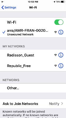
2.1.2 Captive Portal

2.1.3 Enter Token/Password or Get Voucher

2.1.4 Payment

Then connect to the Internet, phone, email, etc.
2.2 Node Loss Performance
Purpose: Show node-to-node Throughput efficiency at 95% or greater
2.3 Captive Portal
Purpose: Show built-in business functionality
As shown in 2.1.2 above, the initial connection with the ARRA system from any platform guides the user to the captive portal. We demonstrated this functionality as well as how to obtain a voucher (see screenshots from 2.1.3 and 2.1.4 above).
2.4 Self-healing Mesh
Purpose: Network traffic automatically rerouted around downed nodes
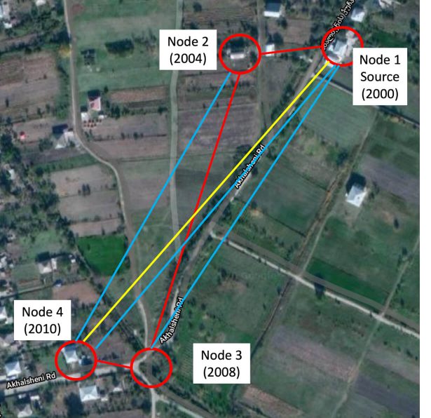
This was demonstrated in the October 6 rural environment tests. We alternately powered down the second and third nodes (see 2.7 below), with no loss in connectivity at the fourth node. As the third node was powered off, the fourth node automatically rerouted to gain its signal from the second node. We powered the third node on, then powered the second node off. The third node automatically switched to get signal from the source (2000), again with no interruption of signal at the fourth node
2.5 High-capacity Scalability
Purpose: Five nodes under load with no signs of overhead stress
In the rural environment demonstration on October 6, we were able to show high-capacity scalability with only four units. This reinforces both the flexibility of the system when deployed, as well as the routers ability to reach more users with fewer units.
Four ARRA routers were deployed across
2.6 Seamless Multi-homing6
Purpose: Show redundant auto-switching through alternate backhaul sources
2.7 Deployment Flexibility
Purpose: Deploy units around obstacles (hills/buildings) without costly towers
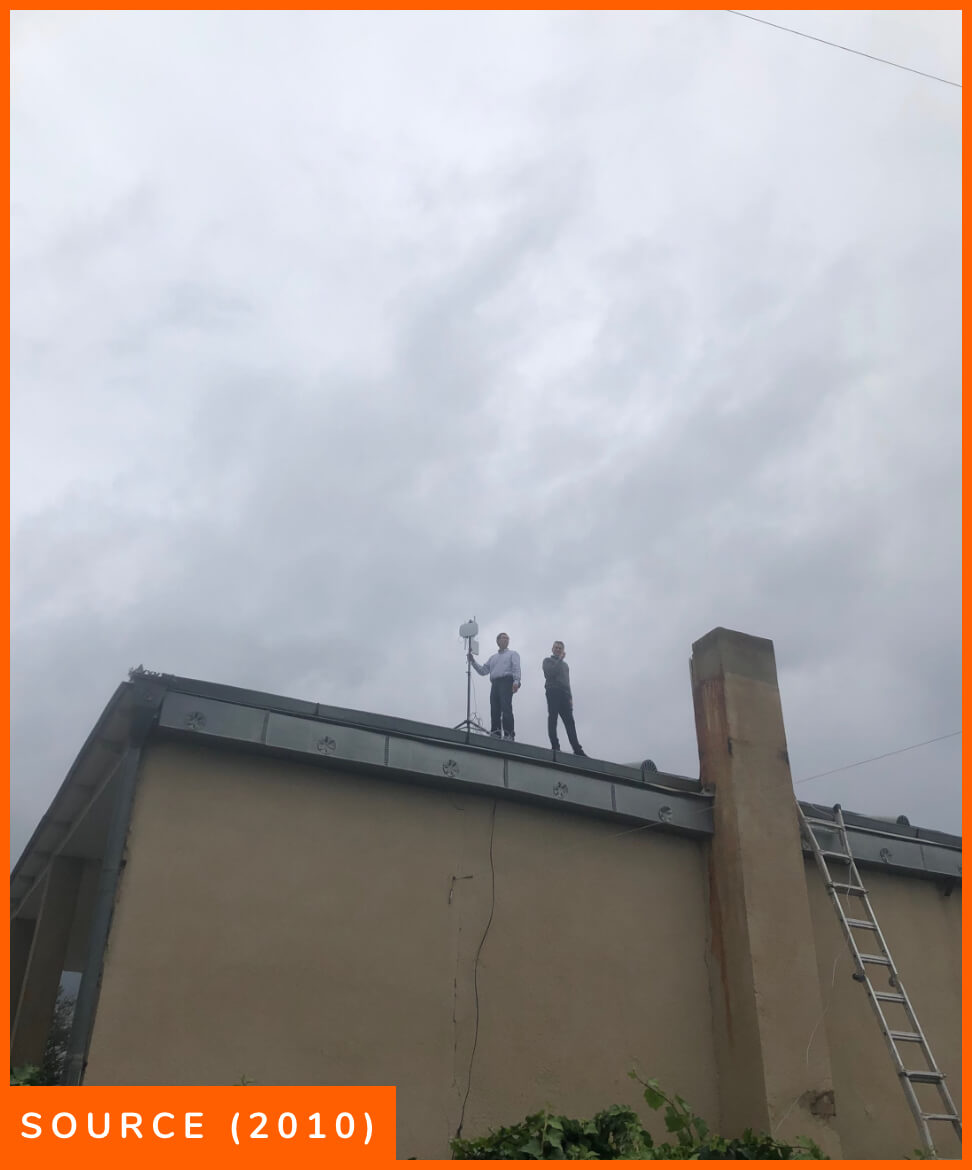
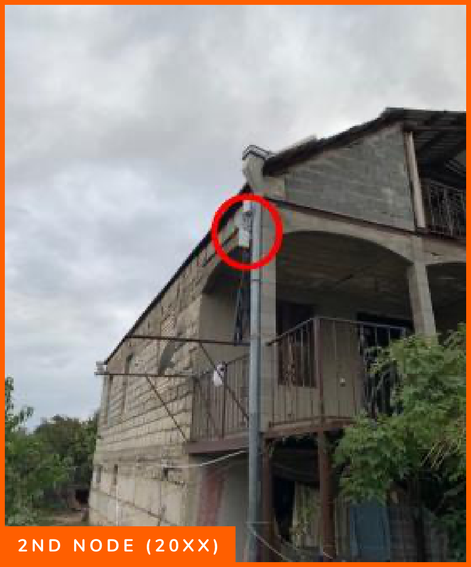
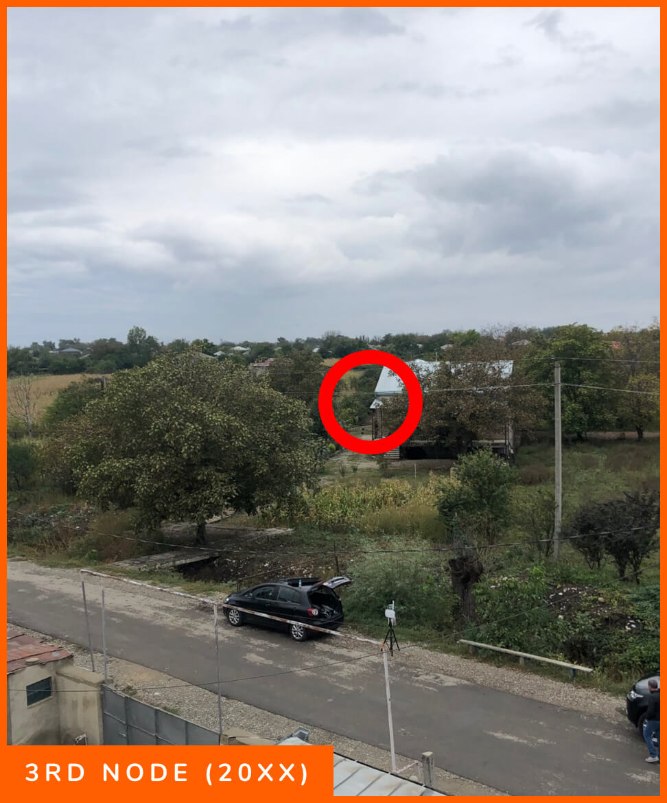
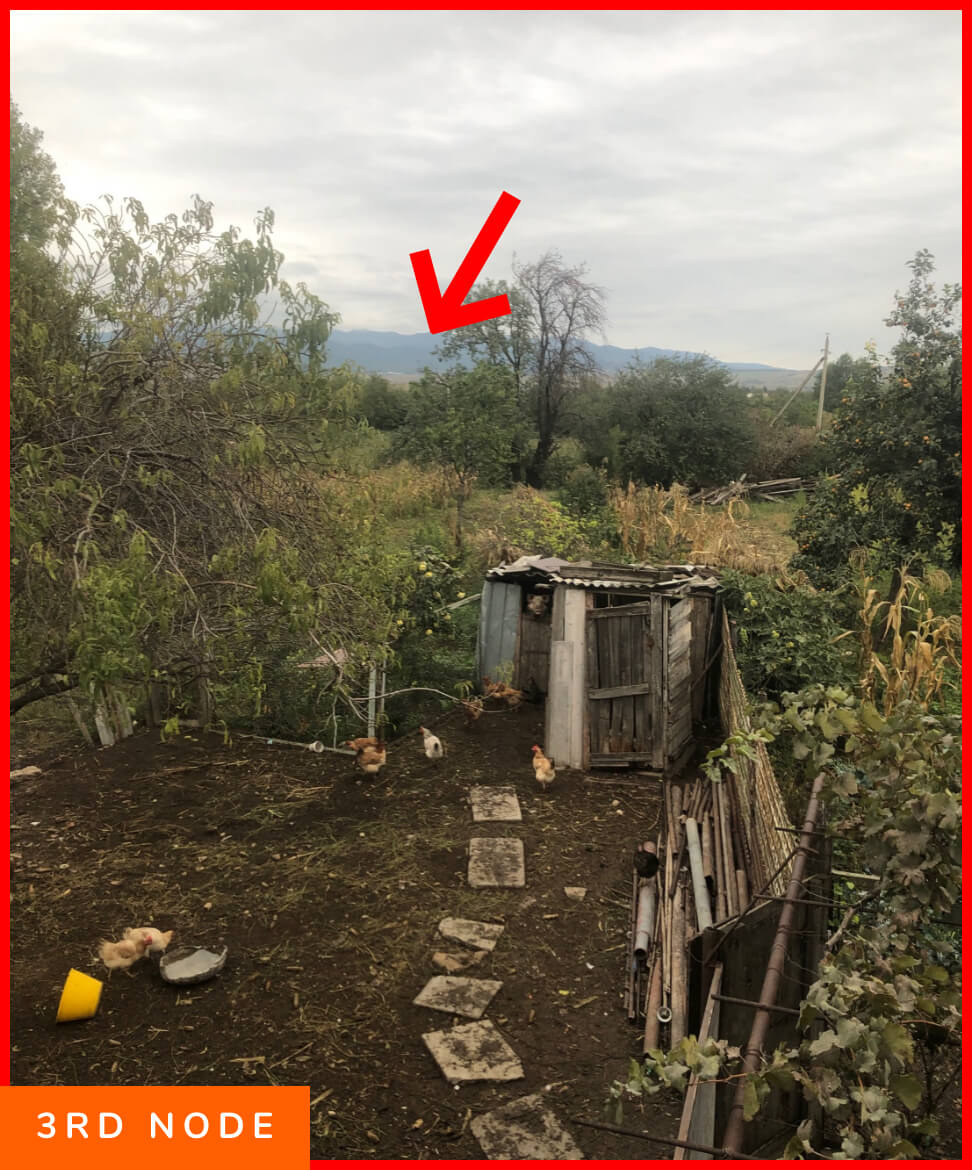
Demonstration of deployment flexibility was impiracally observed as we set up the individual nodes. We adjusted the location of the source unit from the middle of the roof to the southern end of the house in order to have better line of sight to the second node which was initially located behind a stone house.
2.8 Long-range AP Performance
Purpose: Show range connectivity behavior for end users
2.9 Long Range Capability
Purpose: Show long range node-to-node performance (site permitting)
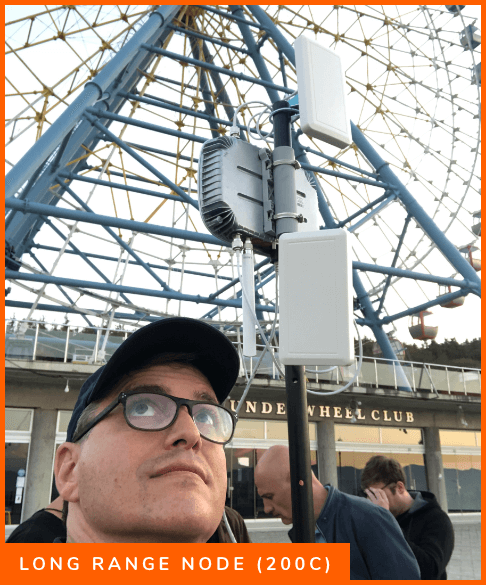
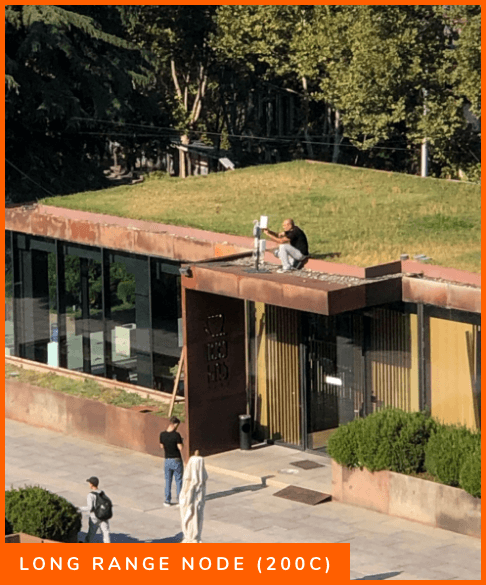
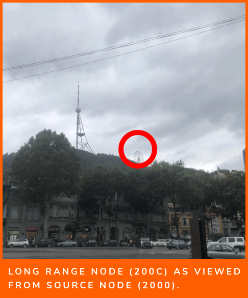
Using conventional antenna’s we exhibited long-range connectivity at 1.8km from the Radisson Blu Hotel to Mtatsminda Park. Signal was measured at 20Mbs at the Ferris Wheel, with an output of 25Mbs at the source.
Test Guidelines
1. Self-healing test:
This tests the mesh’s ability to re-route and continue delivering connectivity after a transit node has gone down. To test this, simply maintain a connection through the internet that shows a live session… like A live skype conversation. Assuming node A is the source of the internet and has backhaul provided to it, then the test should be done while connected to the AP of node D.
At this point, turn off node B and wait to see what happens to the connectivity. The mesh should identify the problem and re-route the connectivity through node C instead. In most cases, there will not be a disruption. If the traffic was mostly coursing through the downed node, then re-routing can take up to 100 seconds. Once it’s observed that connectivity was maintained or properly restored, the test can be repeated using node C.
2. Load distribution and multi-backhaul:
This test demonstrates the mesh’s ability to dynamically distribute backhaul resources across the mesh efficiently. No IP routing table configurations are necessary. It’s all automatic. To perform the test, simply add backhaul to any additional nodes in the mesh and observe its seamless handling of the resource.
3. Confirm business model / captive portal functionality:
This tests the mesh’s ability to operate and respect the business rules that have been assigned to it. The mesh auto-provisions access control, business model workflow, payments, and taxation.
- Set the business model to ‘Hotspot’ and test the mesh’s ability to act as a paid hotspot network.
- Set the business model to ‘open’ and test the mesh’s ability to act as an open network with minimal restrictions.
- Set the business model to Monthly and test the mesh’s ability to operate a full-service ISP autonomously.
4. Test deployment flexibility:
The diamond pattern’s most obvious benefit is the ability to show how the mesh allows you to avoid the traditional cost & complexities of wireless infrastructure. Instead of having to build a tower to get line of sight connectivity, you can add nodes and create low-cost connectivity routes around obstacles. Mesh as a deployment capability saves enormous amounts of time and money.
Mesh nodes can be up to 2 kilometers away from one another. This allows for convenient and low cost spreading of network connectivity with almost no planning or maintenance required.

